FZR"400" project build | Page 12 | GTAMotorcycle.com

FZR"400" project build

Ok now the pipes are on correctly...
photo-670.jpg

Now I have to make my own Y-pipe or I can buy a ready made y pipe and make it fit... any thoughts or suggestions? I want an O2 sensor bung on there to go with the EFI setup that is to come. I know they sell Y-pipes for the 06 + R6s with the O2 bungs on them already but best price I found was $150+ $25 shipping. Hoping to spend less than that considering I got the headers for $86 shipped.
photo-1579.jpg

photo-396.jpg

More views of what I need to do.
 
It's no where near finished. We don't all have money to blow on powder.

if you are blowing on powder your doing it all wrong.....its to be snorted....rails is where its at!
 
Tonight I made a stiffener ring so that I could get the R1 boot to clamp firmly onto the yzf600 boots. So far so good. Going to have to grind it down a little bit and port it to the opening in the boot as not to restrict airflow too much.
This was cut from 1.66" aluminum pipe which on the caliper measure out to be 41.7mm instead of the 42.2mm it's supposed to be. Which is ok for me because the YZF boots are 41mm ID. I think I am going to turn the stiffener down to 41mm or 40.5 for easier boot installation. It sure does seal up nice and tight with the yzf boot though. I know it's a small update but I am getting killed at work so my creative potential after work at the moment is somewhat limited.
photo-1874.jpg

photo-1480.jpg

photo-728.jpg

photo-980.jpg
 
By the way, don't you think you've bled out enough of that green stuff? Time to go blue :cool:
 
By the way, don't you think you've bled out enough of that green stuff? Time to go blue :cool:

I know the kawi is sold, but I will always have a sweet spot for them, whether I ride yamaha or suzuki (cuz no fuckin way am I getting a honda...). Always loved Kawi styling, kawi engines and their design pioneerism comparing to their bigger competitors.

Jk On the honda thing... I could see my self on a CBR900R one day.. but that's probably the only honda I'd own.
 
Again another really tiny update. Made up some proper spacers out of half inch aluminum rod with 1/4" hole drill down the middle. They are approximately 22.5mm long. For those unaware it's the little aluminum spacer between throttlebody 2 and 3 right in the middle.
photo-1400.jpg


Test fit to make sure it's space ok and fits the boots correctly.
photo-309.jpg
 
Lookin' great, man.

Thanks man got some more done tonight...

Just got 4 stiffeners back from my machinist friend. 40.75mm OD 38mm ID and 8mm tall.
photo-1984.jpg


In the boot.
photo-2136.jpg


Top on and tightened. Damn near inseperable.
photo-2333.jpg


Damn iphone camera. Put the buts all back together clamped down good and stuck the throttlebodies in there. I have 50psi fuel line linking the two halves of the fuel rail for now until I can get it welded together.

So basically mechanically speaking everything ready to at least get the bike idling. The only barrier at this moment is doing the wiring up now so that will be my next focus. Integrating the Microsquirt harness with the R6 harness is my next goal. I still need some connectors that connect to the 06/07 R6 fuel pump. I am not exactly sure where I can buy those parts from. And after that I need an IAT sensor and it will be electrically complete.
 
Started wiring up the injectors and various other sensors and Holy **** is all I have to say. I am so damn ignorant when it comes to wiring especially reading wiring diagrams. I have so much to review before I can continue. If anyone wants to come over and educate me I can provide some cold beers and hot meal.

Got the injectors wired up, but when I got the MAP sensor and TPS man oh man.
 
Ok so I have been doing a lot of staring at wiring diagrams and talking it over with a super intelligent fellow (DonTZ) and I think I am ready to have this thing idling this week. I have all the sensors, and I am 99% finished wiring. I just need to hook it all up on the bike. I have done all the wiring I can do to get it to a plug and play state.

Here are some pics to prove I haven't been doing nothing!

Stopped by PA and bought a bunch of stuff
f197cb09.jpg

2a93854c.jpg


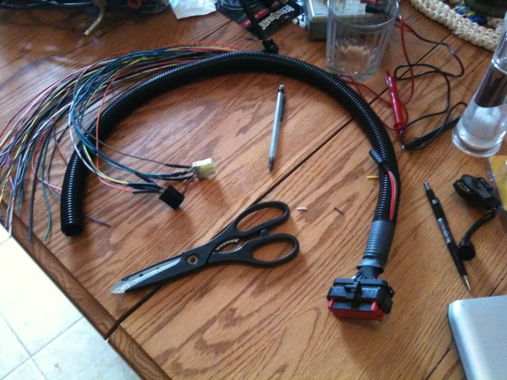
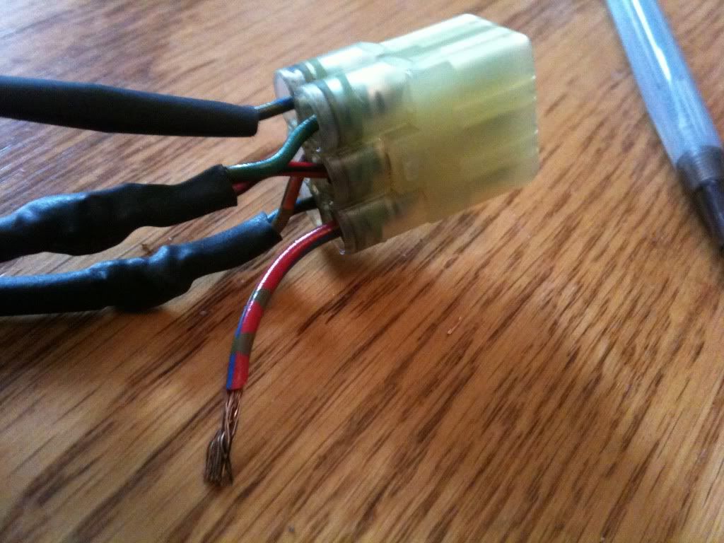
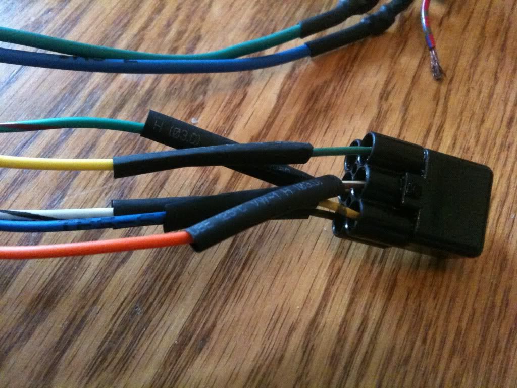
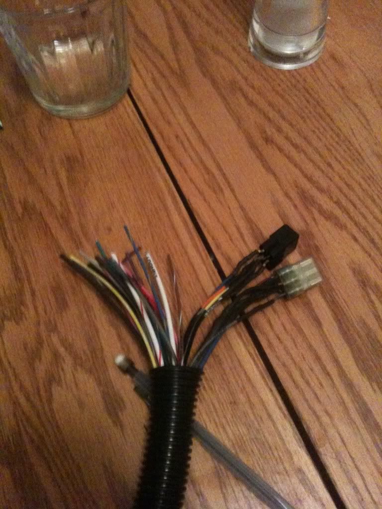
Microsquirt harness with R6 injection connectors soldered on..
photo-982.jpg

photo-1044.jpg


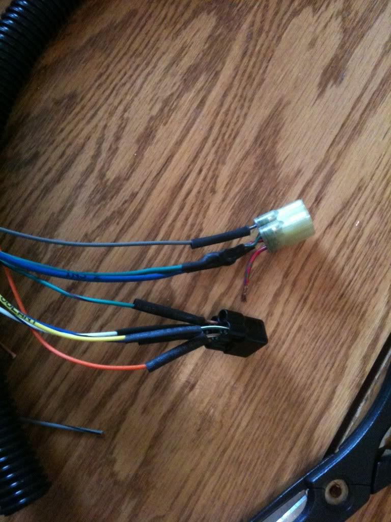
The lonely wire is the injector power (+)
photo-1185.jpg


The other connector is fully wired this one is all inputs from sensors like CLT, IAT, MAP, TPS
photo-628.jpg


All together
photo-215.jpg


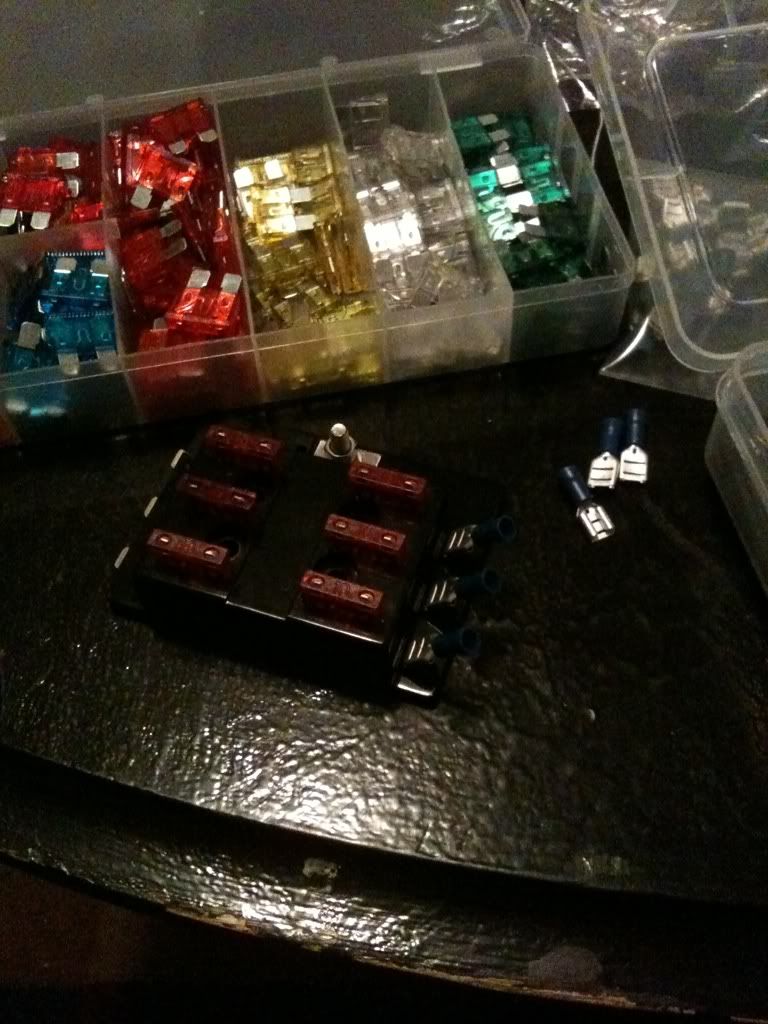
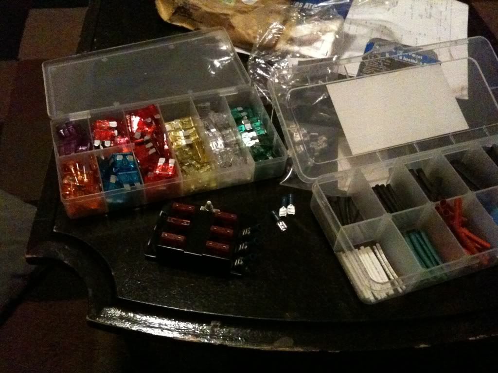
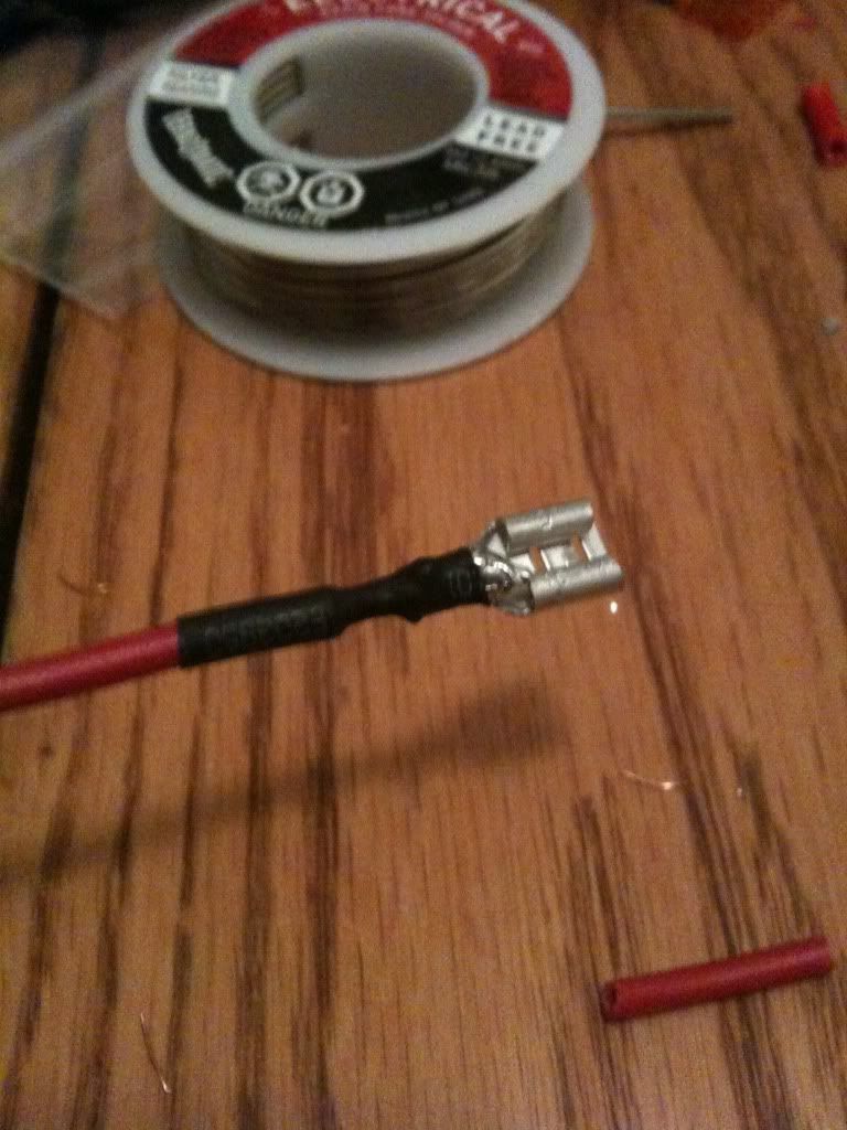
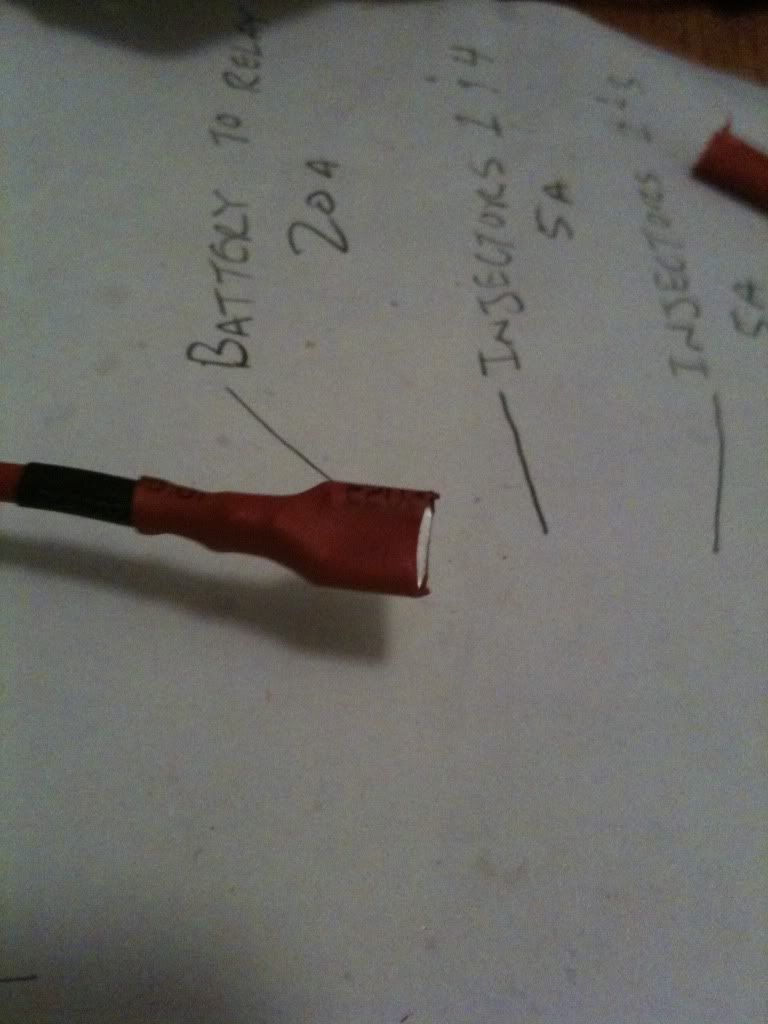
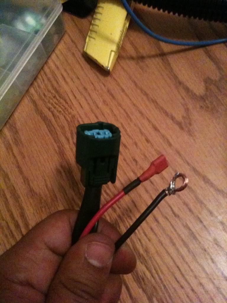
Then I got to making some connectors for my new EFI fuse box that I will run independant of the stock fusebox for easy trouble shooting. Double heat-shrinked for a nice finish.
photo-3.jpg

photo-2.jpg


What you see here is the fuel pump power and injector power
photo-4.jpg


The fuel pump plug that I got off of woodzee here along with a bunch of other stuff... There you can see the connector, power, and ground. The power runs through the fuse box in the picture above. And the ground I looped for easy grounding anywhere.
photo-7.jpg
 
good connectors. glad you are taking your time here. Nothing like a lose wire that causes grief down the line.

Just a suggestion, you might want to put some di-electrical grease in those connectors and blade connectors whille everything is out, long term maintenance.
 
Haven't checked this in a while. Sorry, I should have tried to come over.

Why don't you come by this week and we'll get it idling? I just finished the last of my soldering. Gotta go over the wiring diagram one last time to be sure I want to cut into my Wiring harness.

I want to run this whole circuit off of the main relay so it's turned on and off with the ignition like everything else. So I am thinking of using the wire that goes from the main relay to the CDI unit. The black and blue wire in this diagram:
fetch.php


Basically going to be tapping in with a relay that ECU will turn on and off and that will turn the fuel pump and injectors on and off. So if the 3 amp fuse to the ECU blows, the fuel pump and injectors turn off too, that way they aren't left uncontrolled.
 
Summer sports are here, so I have no time to myself anymore at nights. Maybe a little on weekends. Two kids in different sports that I need to attend and different nights.

On a whim, because the tapping was getting annoying I started to do a valve adjustment on the bike on the weekend. Little did I know, that for the ZX14, since you can't access the top of the engine directly, you have to take apart just about everything to get into it, and this is the first time I've done a valve adjustment on a motorcycle so I just ordered a shim kit today. It won't be here until Wednesday, so the bike probably won't be back together until the weekend.
haha ya I am sure that job will be a pain on the 14.. especially with the wierd shape the frame takes.

On another note do you think the Black/Blue wire is a good call to tap into to do what I described above? Or is there a more recommended route
?
 
CDI would pull a lot of switched power and might be pretty noisy. I would have no way to tell unless I scoped it. I'd just run another relay, but the flying leads I've gotten with aftermarket ECU's usually have the main power relay already connected.
 
CDI would pull a lot of switched power and might be pretty noisy. I would have no way to tell unless I scoped it. I'd just run another relay, but the flying leads I've gotten with aftermarket ECU's usually have the main power relay already connected.

Oh I explained poorly. I am running another relay off that line. I am just using it as my "On" switch.
 
Yes, no problem. Any switched power will work then.

http://www.msextra.com/doc/general/ms2external.html

If you look at the diagram posted there:

What I did was take my fuel pump relays 85 and 87 wire and coupled those two to the line going to the 3a fuse. So now I have 3 wires meeting in one spot. Then I am going to plug that into the black/blue wire on the FZR which is the CDI feeds from the main relay or would be similar to the wire 30 on the msextra diagram.

Did I do that correctly? I wish I wasn't so dumb at this stuff haha. But I don't want to burn up my $400 ECU.
 

Back
Top Bottom