Suzuki Marauder Rebuild - (VZ800)

I am assuming this wasn't a writeoff? It would suck to put the time and money in and end up with something that had to be sold out of province.
 
Headlamp Build

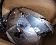
Old headlamp isn't doing too hot. The options are OEM replacement from a parts bike, fitting in a aftermarket 7" lamp holder, or full DIY.

20240918_135546.jpg
20240918_135516.jpg

I wanted to try my hand at fabricating as much as I could out of parts I had around me. The cyberpunk aesthetic pushed me toward something LED based, and angular. I also wanted a wider beam pattern, but still narrow in height. Original lamp focused light within about 10° vertically, so I wanted to keep within that.

I had a pair of Alpena Tecslim 7" light bars that I was planning on using as fog lights on my car. I measured my front bumper incorrectly so they were just gathering dust in my closet. The mounting hardware included didn't fit the application.

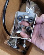
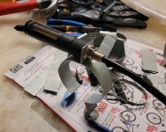
First step was to make a set of brackets or clamps that would allow me to mount two light bars to the front, securely, and adjustable. I also bought aftermarket turn signals since the OEM ones on the back ripped off. I needed to incorporate them into my solution as well.

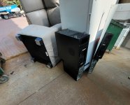
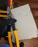
In the spirit of DIY, a trip to the building dumpster yielded access to soft sheet metal that I could cut with snips and maybe shape with a set of files.

20240918_134727.jpg
20240918_134945.jpg

Turn signals ordered from here (AliExpress link).

20240821_185007.jpg

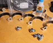
I glued thin rubber shims to the underside of the clamps to help them stay in place. I tested them out without the strip and they stayed in place fine, but all the same.

On the front of the clamps, I went with 6mm holes to match the M6 bolts from the original light bar hardware kit. On the back end, a 10mm hole to match the M10 turn signals. All clamps were drilled the same, not sure why. Should have thought this through because now I needed larger bolts for the bottom clamps where there are no turn signals at the back.

20240905_212822.jpg

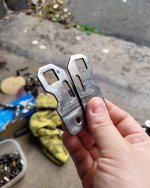
To retain vertically positioning, I reused the L mounting brackets that came with the lights. Heat with propane and hammer flat.

20240827_185353.jpg

I needed a strip to run, on each side, between the top and bottom light bars, to keep them from vibrating excessively, and make the whole fixture more rigid.

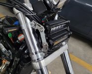
Flat washers were used to center the light bars between the clamps, adding a couple mm of offset. I also needed to space the bottom clamps apart more than expected. All clamps were sized for the 54mm section of the forks, but after alignment and leaving space for the speedometer and other cables, I had to move the bottom clamps down to the 56mm section.

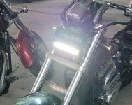
The final look ended up like this.

20240918_134618.jpg

Still adjusting cable management on the back end, may need to shorten some excessively long wires. I split the old bulb harness with bullet connectors, so it's easy to return all modifications to stock.

Bottom light wired to low beam circuit, top light wired to high beam. Consumption of both lights combined is well below the most the circuit would see from the original bulb.

20240918_144925.jpg

Better pictures will follow. (Parts bike in the background).
 
Last edited:
Headlamp Rebuild

Old headlamp isn't doing too hot. The options are OEM replacement from a parts bike, fitting in a aftermarket 7" lamp holder, or full DIY.

View attachment 69783
View attachment 69784

I wanted to try my hand at fabricating as much as I could out of parts I had around me. The cyberpunk aesthetic pushed me toward something LED based, and angular. I also wanted a wider beam pattern, but still narrow in height. Original lamp focused light within about 10° vertically, so I wanted to keep within that.

I had a pair of Alpena Tecslim 7" light bars that I was planning on using as fog lights on my car. I measured my front bumper incorrectly so they were just gathering dust in my closet. The mounting hardware included didn't fit the application.

First step was to make a set of brackets or clamps that would allow me to mount two light bars to the front, securely, and adjustable. I also bought aftermarket turn signals since the OEM ones on the back ripped off. I needed to incorporate them into my solution as well.

In the spirit of DIY, a trip to the building dumpster yielded access to soft sheet metal that I could cut with snips and maybe shape with a set of files.

View attachment 69786
View attachment 69788

Turn signals ordered from here (AliExpress link).

View attachment 69789

I glued thin rubber shims to the underside of the clamps to help them stay in place. I tested them out without the strip and they stayed in place fine, but all the same.

On the front of the clamps, I went with 6mm holes to match the M6 bolts from the original light bar hardware kit. On the back end, a 10mm hole to match the M10 turn signals. All clamps were drilled the same, not sure why. Should have thought this through because now I needed larger bolts for the bottom clamps where there are no turn signals at the back.

View attachment 69787

To retain vertically positioning, I reused the L mounting brackets that came with the lights. Heat with propane and hammer flat.

View attachment 69790

I needed a strip to run, on each side, between the top and bottom light bars, to keep them from vibrating excessively, and make the whole fixture more rigid.

Flat washers were used to center the light bars between the clamps, adding a couple mm of offset. I also needed to space the bottom clamps apart more than expected. All clamps were sized for the 54mm section of the forks, but after alignment and leaving space for the speedometer and other cables, I had to move the bottom clamps down to the 56mm section.

The final look ended up like this.

View attachment 69792

Still adjusting cable management on the back end, may need to shorten some excessively long wires. I split the old bulb harness with bullet connectors, so it's easy to return all modifications to stock.

Bottom light wired to low beam circuit, top light wired to high beam. Consumption of both lights combined is well below the most the circuit would see from the original bulb.

View attachment 69794

Better pictures will follow. (Parts bike in the background).
Those look interesting but how is the beam? Shoot a pic of them hitting a garage door or wall. Are you planning on riding this in the dark or daytime only?
 
Those look interesting but how is the beam? Shoot a pic of them hitting a garage door or wall. Are you planning on riding this in the dark or daytime only?
Will take a night time pic this evening after the Burger meet.

I have used them on a trip to Collingwood this past weekend and the forward throw was acceptable, the lateral throw was a bit bonkers (vary wide). May need to look into a way to refocus the last LED or two on either end.

The vertically pattern is listed as 15° which sounds a bit much, but in practice it was ok. You'll see soon.
 

Battery & Charging System Upgrade

Preface​

Why fix something that isn't broken?
In Canada, and for the average rider, motorcycling isn't a common mode of transportation—it's more of a seasonal hobby. Approaching it this way offers better insight into why we often fall for the allure of farkles.

Case in point: installing a lithium battery on an old motorcycle, and the trials and tribulations that follow—documented for your reading pleasure below.


Part 1 – The Future Is Awesome​

Ever since I got this motorcycle, I’ve been giddy and eager to tinker with the electrical system—cleaning connectors, rewrapping broken cable insulation, optimizing wire paths, modernizing components. It’s a long list.

Have you seen Amphenol’s Sine System AT series connectors, or the Deutsch automotive catalogue? (Avoid the Deutsch AS catalogue if you have trypophobia.)

The same could be said about the controls, relays, ignition system, lighting, and ultimately, the charging system.


Part 2 – Finding a Problem for the Solution​

I wasn’t planning on bedazzling my motorcycle with lights or installing an audio system specifically tuned to torture innocent dogs 10 kilometres away. If anything, swapping all bulbs to LED would reduce the system’s overall demand.

SLA batteries are cheap, reliable, and a known entity that’s been around longer than I have. In terms of weight savings, the ~5 lb I’d save could be shaved off with a few fewer burgers and a healthy bowel movement. I was having a hard time finding logical loops to jump through to justify this project.

There’s also the part where I might need a new regulator/rectifier to play nice with the lithium battery—unless I want my motorcycle to burn down. The upshot? There’d be nothing left to bolt a farkle to.

Ultimately, I settled on the increased cranking amperage and significantly reduced self-discharge rate as healthy justifications. For a similarly sized lithium battery, the CCA is double that of an SLA battery. There have been a few times when it hesitated to start—either after sitting for a few days or after riding on a very hot day. Let’s say I’m addressing that.

As for the self-discharge, this mostly helps with my laziness and the occasional tripping hazard in the apartment. With the SLA battery, I have to pull it and leave it connected to a tender upstairs over the late winter months or when not riding for a while. Most of the time, this ends up being between the dining room and kitchen—tile floor and good airflow. The SLA battery isn’t old; that just seems to be its nature.


Part 3 – Feeding the Habit​

Lithium batteries have come a long way, and prices have dropped over time as competition in the market has grown. That said, the same applies to AGM (SLA) batteries.

On the low end, a similarly sized lithium battery to what’s currently in my Marauder is around $120. You can venture into the dark realm that is the internet and get something for as low as $70—but YMMV. SLA batteries seem to be in the same ballpark: pre-filled Yuasa coming in at $107, and venturing south to $58.58 for a Mighty Max gel battery (also SLA) from Home Depot.

I managed to get my hands on a BNIB Noco NLP14 for $70, tested to make sure it wasn’t a dud, and the course was set. I had to get a compatible trickle charger to confirm the battery is healthy until the rest of the charging system is sorted out.

As is tradition, I approached this back-asswards.

Now comes the fun part: rectifiers and regulators!


Part 4 – Rectifiers and Regulators​

When I was looking into reviews of lithium powersport batteries—specifically Noco—a common theme emerged: bikes on fire, left, right, and centre. Mostly cruisers. What gives?

One possibility is that older rectifier/regulators are SCR (thyristor) based, compared to the relatively newer MOSFET-based designs. There are some design elements worth considering when identifying the causes of the moto-flambé (café-flambé?).

Before I fall off into another tangent, I’ll keep the topic limited to permanent magnet alternators (PMA). Field coil regulated systems for motorcycles do exist, but they’re out of scope for this project.

In this context, both SCR and MOSFET-based regulators operate as shunt-type regulators. In short, any excess power generated by the stator and not consumed by electrical components is returned to the stator—with varying degrees of efficiency. In both cases, the rectifier circuit primarily monitors battery voltage to determine when to shunt power; for the Marauder, this is around 14.5V.

A big difference is that SCRs have significantly higher resistance compared to MOSFETs, running much hotter. This is usually a way to identify the regulator type: an SCR regulator will become uncomfortably hot after a while—as is my case.

Both types are susceptible to failure from overheating, but it doesn’t take much thought to figure out which one reaches the failure point faster. When they do fail, both can fail closed, allowing the stator to give ’er all she’s got—exposing the battery and the rest of the circuit to 50+ volts.

Normally, this would cause an over-current situation and blow a fuse, ending the drama. But tolerances in electronic components being what they are, some things blow faster than others. A lithium battery’s BMS should be able to handle a voltage or current spike—within design tolerances—but the opportunity for failure is not zero.

This is all to say: a modern MOSFET regulator is the way.

(Currently shopping for one.)
 
Back
Top Bottom