Garage Door Opener wired to handle bars | GTAMotorcycle.com

Garage Door Opener wired to handle bars

oioioi

Well-known member
Site Supporter
I am once again thinking ahead to winter projects and I know I want to wire in a garage door opener on the bike.

I had one on the R6 back in the day. A garage door opener with with a momentary switch wired/soldered onto the opener. The switch was mounted in a convenient place and the garage door opener sat under my seat.

I may go with this option again but purchase a different button. Handle bar mounted one.
Amazon Link
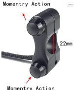
1664675727835.png

I also came across a write up on how to do this with the high beam switch as well.

Installing a Garage Door Opener Wired to Motorcycle Hi-Beam

Similar idea but no additional button on the handle bar.

I am not sure which way I will go yet as I currently have Aux lights (1 on each side mounted to the factory crash bars) wired to the high beams. The high beams button also has the ability to be a momentary button to flash the high beams only as a passing flash. Conveniently located to use your index finger to flick the switch.

I figured I would share this in case others want to do this as well or have better options.
 
Hey Google, open my garage door.

$40 solution, no bike wiring, works from your car too.
 
The previous owner of my Goldwing had an opener triggered by a toot of the horn. I never used it.
Ya. That wouldn't be a good idea for the neighbours.
 
Hey Google, open my garage door.

$40 solution, no bike wiring, works from your car too.
I like that better. I wouldn't want to press the opener button every time high-beams got triggered. It just seems like something that would go wrong eventually (eg go on a trip and you have pressed the garage door button hundreds of times before you return, are they out of sync).
 
I am leaning towards a secondary button

I don't mind doing the little wiring required.


As much as my garage door is internet ready I don't have much faith in "hey google" with a helmet on and communicator
 
I am leaning towards a secondary button

I don't mind doing the little wiring required.


As much as my garage door is internet ready I don't have much faith in "hey google" with a helmet on and communicator
I like adding buttons/switches up under a fairing somewhere. Easy to reach, no visual clutter. Muscle memory is good enough to pop a garage door so I don't need my eyes and one hand off the bar isn't a big deal at that time. For a garage door, I might put it on the right so I could be lazy and use clutch while I waited for door to open instead of needing to go to neutral.
 
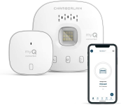
I don't know what type of garage door you have, but a spare for mine is about $30 from Liftmaster, or $15 for a Generic no-name. For $40 you can get one of these and control by your phone from anywhere:


View attachment 57827
Already have the app..
A simple press of a button much easier to do than stopping at the end of the driveway and pulling out the phone, taking gloves off...…..
 
Glad someone found it useful
 
More than I want/need to spend on it
 
So I finally got around to doing this garage door opener button. Easily accessible on my handlebars.

Forgive me, but this is my first “how-to” write up.

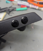
I played with a few ideas on where to mount the buttons and which buttons to get. I initially thought of mounting them on the left handle bar, but after another member pointed out that the right side would most likely be better as you are most likely off the throttle while pulling up to your driveway. I went with the throttle side. On my bike 2020 VStrom 1050, I found a perfect spot for the 2 buttons. In my case I installed 2 buttons as I have 2 single garage doors. Even though I roll out of only 1 side, 99% of the time, I wanted to have the option for both.

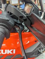
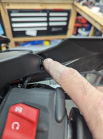
Quick picture of the location of buttons on the handle bar. Easily accessible with the index finger.
The buttons were purchased from AliExpress. Link below. I used a 2 conductor cable from an old DC power supply. In my application, because I wired up 2 separate buttons, I needed 2 separate cables. I also had some nylon cable sleeves from some broken phone charging cables. I decided to place the 2 DC cables into the sleeve to keep them a little more tidy. I quickly found that this made the cable much more stiff but still workable.

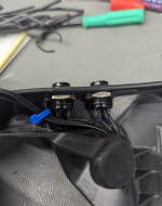
The cables were soldered directly onto the pins on the back of the buttons, and some shrink wrap was used to cover as much of the exposed solder joints as possible.

On the remote side, I decided to add a pair of JST connectors (link below) should I need to remove the remote in case of a sale of the house or bike. This way the buttons would stay on the bike bike and a new remote can be added easily.

The DC cables were routed along the bike with the other cables from the handle bars. Making sure that they are not interfering with anything or restricting the movement of the handle bars.

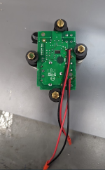
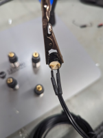
The JST connectors were soldered onto the pins on the back of the circuit board. I identified the pins by cross connecting the 2 pins with a short cable to simulate pressing the actual button.

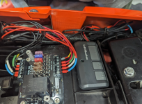
I placed the actual remote under the seat. It is currently in the original casing but I plan on having a small “project” box 3D printed or find one that fits the spot where I want to mount it.

I also put some shrink tubing over the JST connectors to make sure they do not disengage and are protected from water/moisture.

Overall I am happy with the outcome. This was inexpensive and more satisfying on a personal level. I prefer the DIY methods over read made products that are often more costly than I want to spend.

Links of items used.
JCT connectors
https://www.aliexpress.com/item/329....order_list.order_list_main.15.21ef1802VM7FJW
Small momentary button
https://www.aliexpress.com/item/100....order_list.order_list_main.40.21ef1802VM7FJW

Garage Door opener.
https://www.amazon.ca/3-Channel-Uni...9Y2xpY2tSZWRpcmVjdCZkb05vdExvZ0NsaWNrPXRydWU=

DC Cable:
https://www.aliexpress.com/item/1005001893554237.html?spm=a2g0o.productlist.main.29.1ea35de8u6V1C8&algo_pvid=d055910a-327f-4e57-8dcd-62c5e6365864&aem_p4p_detail=202302141702178309741307703270002195475&algo_exp_id=d055910a-327f-4e57-8dcd-62c5e6365864-14&pdp_ext_f={"sku_id":"12000031340826273"}&pdp_npi=3@dis!CAD!12.13!6.67!!!!!@0b0a558a16764229375255052d0736!12000031340826273!sea!CA!2331427807&curPageLogUid=94aefTGI0tAd&ad_pvid=202302141702178309741307703270002195475_3&ad_pvid=202302141702178309741307703270002195475_3


Any comments or questions, feel free to post away.

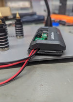
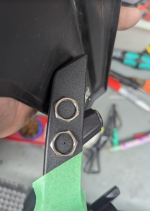
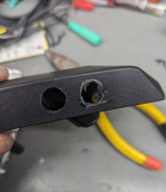
Here are some other progress photos.
1676423523203.png1676423537345.png
1676423592273.png1676423606533.png
1676423674816.png1676423694320.png
1676423709766.png1676423719526.png
1676423637351.png1676423796180.png
 
Last edited:
So I finally got around to doing this garage door opener button. Easily accessible on my handlebars.

Forgive me, but this is my first “how-to” write up.

I played with a few ideas on where to mount the buttons and which buttons to get. I initially thought of mounting them on the left handle bar, but after another member pointed out that the right side would most likely be better as you are most likely off the throttle while pulling up to your driveway. I went with the throttle side. On my bike 2020 VStrom 1050, I found a perfect spot for the 2 buttons. In my case I installed 2 buttons as I have 2 single garage doors. Even though I roll out of only 1 side, 99% of the time, I wanted to have the option for both.

Quick picture of the location of buttons on the handle bar. Easily accessible with the index finger.
The buttons were purchased from AliExpress. Link below. I used a 2 conductor cable from an old DC power supply. In my application, because I wired up 2 separate buttons, I needed 2 separate cables. I also had some nylon cable sleeves from some broken phone charging cables. I decided to place the 2 DC cables into the sleeve to keep them a little more tidy. I quickly found that this made the cable much more stiff but still workable.

The cables were soldered directly onto the pins on the back of the buttons, and some shrink wrap was used to cover as much of the exposed solder joints as possible.

On the remote side, I decided to add a pair of JST connectors (link below) should I need to remove the remote in case of a sale of the house or bike. This way the buttons would stay on the bike bike and a new remote can be added easily.

The DC cables were routed along the bike with the other cables from the handle bars. Making sure that they are not interfering with anything or restricting the movement of the handle bars.

The JST connectors were soldered onto the pins on the back of the circuit board. I identified the pins by cross connecting the 2 pins with a short cable to simulate pressing the actual button.

I placed the actual remote under the seat. It is currently in the original casing but I plan on having a small “project” box 3D printed or find one that fits the spot where I want to mount it.

I also put some shrink tubing over the JST connectors to make sure they do not disengage and are protected from water/moisture.

Overall I am happy with the outcome. This was inexpensive and more satisfying on a personal level. I prefer the DIY methods over read made products that are often more costly than I want to spend.

Links of items used.
JCT connectors
https://www.aliexpress.com/item/329....order_list.order_list_main.15.21ef1802VM7FJW
Small momentary button
https://www.aliexpress.com/item/100....order_list.order_list_main.40.21ef1802VM7FJW

Garage Door opener.
https://www.amazon.ca/3-Channel-Uni...9Y2xpY2tSZWRpcmVjdCZkb05vdExvZ0NsaWNrPXRydWU=

DC Cable:
https://www.aliexpress.com/item/1005001893554237.html?spm=a2g0o.productlist.main.29.1ea35de8u6V1C8&algo_pvid=d055910a-327f-4e57-8dcd-62c5e6365864&aem_p4p_detail=202302141702178309741307703270002195475&algo_exp_id=d055910a-327f-4e57-8dcd-62c5e6365864-14&pdp_ext_f={"sku_id":"12000031340826273"}&pdp_npi=3@dis!CAD!12.13!6.67!!!!!@0b0a558a16764229375255052d0736!12000031340826273!sea!CA!2331427807&curPageLogUid=94aefTGI0tAd&ad_pvid=202302141702178309741307703270002195475_3&ad_pvid=202302141702178309741307703270002195475_3


Any comments or questions, feel free to post away.

Here are some other progress photos.
View attachment 59500View attachment 59501
View attachment 59502View attachment 59503
View attachment 59505View attachment 59506
View attachment 59507View attachment 59508
View attachment 59504View attachment 59509
Is there still a battery in the remote or are you powering it from the bike? A tiny buck converter would work but make sure you have power switched with key as they can be power hungry.
 
Is there still a battery in the remote or are you powering it from the bike? A tiny buck converter would work but make sure you have power switched with key as they can be power hungry.
I left the original CR2032 battery in there. Well, I replaced it with a fresh one.
This isn't a critical add on so even even the battery dies, its a simple fix. I would hate to have a tiny buck converter drain the battery in case it decided to stop working properly.
 

Back
Top Bottom