FZR400 winter overhaul | Page 4 | GTAMotorcycle.com

FZR400 winter overhaul

Lookin good man. Appreciate the effort to post pics and share with the community.

Curious about your lubrication issue at high revs. Is it confirmed its due to low oil pressure? I've found it to often be from pump acting to quickly and causing cavitation. Can be solved by slowing the pump and running lighter oil. Makes a lil more power too....

Dude, on the crankcase, try Anerobic gasket maker. I always use it. It won't leave cured material inside your motor, and you won't be in a hurry to assemble, especially if humidity is high. If you want to check it out without buying( it's pricey), stop by, I'll squirt some out for you to sample.
 
That'll have to wait until next time :)

No idea on the cavitation issue; how would you tell? On this engine, I'm not that concerned about finding the last 0.01 horsepower, I just want it to last. I suspect that the usual real reason for oil starvation is actually the backed-out restrictor jets that I already fixed. A little more pressure before the relief valve opens is more like a wee bit of extra insurance.

I know that if one uses Motul 300V oil in these engines, it foams up but this doesn't appear to do any damage, and this can be completely fixed by changing to a different oil. (I've been using Rotella for years, including in this one.)
 
Brian,

What gasket kit are you using? Athena? Or are you getting the Yamaha gaskets? I have to pick up another kit, and was wondering if there's any alternatives I missed.
 
That'll have to wait until next time :)

No idea on the cavitation issue; how would you tell? On this engine, I'm not that concerned about finding the last 0.01 horsepower, I just want it to last. I suspect that the usual real reason for oil starvation is actually the backed-out restrictor jets that I already fixed. A little more pressure before the relief valve opens is more like a wee bit of extra insurance.

I know that if one uses Motul 300V oil in these engines, it foams up but this doesn't appear to do any damage, and this can be completely fixed by changing to a different oil. (I've been using Rotella for years, including in this one.)

Id say its often most evident on wrist pins, but could show anywhere where wear is typically found.

Pop an oil gallery plug and hook up a pressure gauge and see what's happening. If you have the required pressure and still see rapid wear, it could be cavitation. It can cause pitting in the pump itself too.

I like slightly lighter oil in a race bike. Helps with cooling, and at high RPM's things don't have to work as hard. Slowing down the pump helps too, just don't leave your bike sitting hot at slow idle for long. I suppose it's tricky to design a lubrication system to cover such a range of RPM's.

No **** on the Motul. I'll keep er in mind. I never use it anyways though, but I'm biased.
 
Pics later. I got one of the more miserable assembly chores done ... installing the cylinder block over the pistons. I have always had trouble with this. Unlike car engines, or many newer bike engines, where the pistons go in from the top one at a time and you can use a normal piston ring compressor to do it, this one is a typical older design with a separate cylinder block that has to go over the pistons with the pistons already on the crank. On a 4-banger, that means you have to do two pistons at a time. There's a chamfer at the bottom of each cylinder, but it doesn't seem to help. The ring pops out of the ring groove and now you can't get at it because it's up inside the chamfer.

I ended up bending the 2nd compression ring on cylinder #3 while doing this. I replaced it with one of the original compression rings in order to get the job done. (Had I damaged the top ring or one of the oil rings, I'd be more concerned, but the 2nd ring isn't quite so critical.) I HATE this feature of older bike engines. The newer setup might not allow cylinder re-boring or replacement as easily but it's sure a whole lot easier to put together. Anyhow, it's done, and the assembled crankshaft and pistons turns by hand quite nicely.

So with the engine together up to the head gasket, it's time to tackle the cylinder head and fix the known issue discussed on page one. I have all the intake valves out. At some point, many moons ago, someone did a very beautiful job of making the intake ports way too big, presumably at great expense. I'm sure it works fantastically on a flow bench. In the engine ... not so much. Weak low-end and mid-range, then around 10,000 rpm, it hits - but still, my stock engine was stronger. So, now I'm going to do my best to un-do it (and probably go in the other direction - smaller) but first - math time.

When the piston is at peak speed (halfway down the intake stroke), we want the nominal flow speed in the intake ports to be somewhere near 0.5 mach (speed of sound) near the peak-power RPM. Flow losses start getting significant at mach 0.6 so we don't want to go there. By establishing a high-velocity column of air in the intake port, when the piston stops near the bottom and turns around, the flow in the intake port hasn't gotten the message yet, so it continues ramming the cylinder with more intake charge. A "lazy" slow intake port will let the flow turn around and let some of the intake charge back out again.

Select 13,000 rpm for that nominal RPM (14,000 on the tach is 13,000 in reality). Each cylinder is 100 cm3 and has to be filled in (nominally) half a revolution.

100 cm3 x 13000/60 x 2 = 43,333 cm3/sec average flow rate over the intake stroke
The peak piston demand is 3.14159/2 times higher than the average, so 68,068 cm3/sec
Speed of sound at normal temperature is close to 340 m/s = 34000 cm/s

So with that known, what's the flow speed at various points and how does it compare to the speed of sound ...

Through the valve curtain area. Intake valve lift less the valve clearance is about 8.1 mm (0.81 cm) and the diameter of the valve seat contact area is approx 20mm (2 cm) and there are two of them. The curtain area is 2 x 0.81 x 2 x 3.14159 = 10.2 cm. The flow is going at roughly a 45 degree angle at this point so effectively this becomes 7.2 cm2. Flow velocity = 68068/7.2 = 9453 cm/s = 94.5 m/s, about mach 0.28. In reality it is probably a little higher because in the area where the two valves are next to each other, the flow area is not fully utilized.

Through the valve seat. Diameter is 18.7mm and there are two of them less two 4.5mm valve stems. Area = 2 x (1.87^2 - 0.45^2) x 3.14159/4 = 5.175 cm2. Flow velocity = 68068/5.175 = 13153 cm/s = 131.5 m/s, about mach 0.39.

The problem is that the porting job has made the valve seat the smallest cross-sectional area in the port ... everywhere upstream is bigger than this and therefore slower.

To get to mach 0.5 = 17000 cm/s we need a flow area of 68068/17000 = 4.0 cm2. In the area ahead of where the valve stem projects through, this requires two holes 16mm diameter (it's about 19mm now).

It's going to take a lot of JB Weld to get there from here.

It's also apparent from the above calculation that there is no purpose to using higher-lift camshafts. There is already more than enough flow area through what's there with the stock camshafts.
 
Last edited:
I ended up bending the 2nd compression ring on cylinder #3 while doing this.

I've done the same when I went up a 1/2mm on an old bike... except I didn't notice until it broke off about 1500 km's later and I heard it. Thankfully the damage was limited to scoring the one cylinder. I went up another 1/2mm on #1 then brought the new #1 piston, wrist pin and all associated hardware along with the existing #4 in to a race shop and they ported it down to the same weight. Re-assembled it and all was golden. That was in the mid-90's and that bike is still running strong today!
 
^ Ouch. Having to do things twice stinks. Been there ...

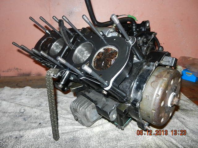
Update time. Here is the engine assembled up to the head gasket with the flywheel installed ... and there is an invisible trick here: the flywheel is assembled without the locating key such that the ignition timing is advanced about 3 degrees. Free timing advancer! The bolt on the end holds the flywheel (which has the tabs for the ignition pickup coil on the outside) on the tapered end of the crankshaft. The key doesn't transfer any of the load - it only holds orientation while the bolt gets tightened. That taper holds the flywheel VERY tightly (to the point of being very difficult to remove). VW diesels have their timing pulley secured to the camshaft in exactly the same way (taper, no key, the orientation is held with a locking tool while tightening the bolt) and that's an even more critical application. What made this possible (and easy) is that the cylinder head is off, so it's very easy to see and measure where exact top-dead-center is. Note the brand new crosshatch pattern in the cylinders.


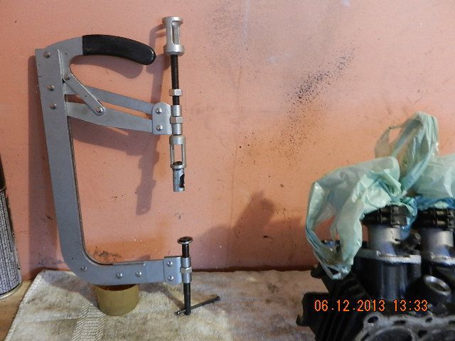
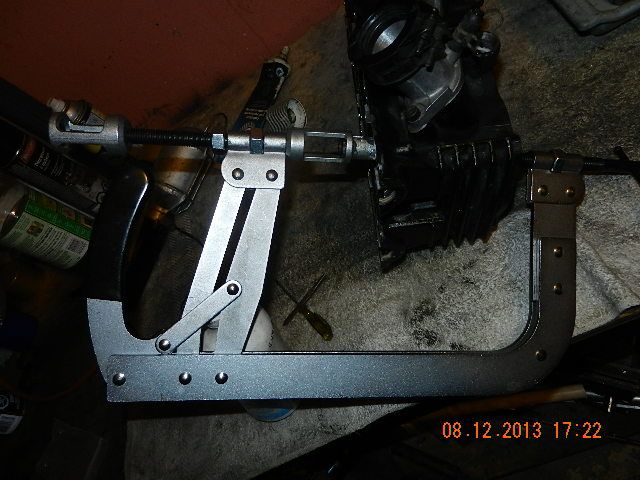
The next step involves this ... a valve spring compressor from Princess Auto, that has been modified to suit this engine. This tool being originally designed for cars, the fixtures that it comes with are too big for the valves in this engine. So, that extra little smaller-diameter piece with the window in it is something that I made up, and there is a rubber washer in the pocket at the bottom that allows the smaller-diameter valve to be clamped (and the rubber washer distributes the force evenly without any chance of causing scratches or other damage to the valve).


I didn't take pictures of the disassembly and modifications made to the intake ports, because the insides of intake ports don't photograph too well. But essentially, if you want to do some reading on what I did, here is something to dig through: http://www.mototuneusa.com/power_news_--_think_fast.htm

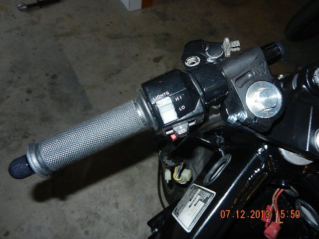
On a completely unrelated matter, I installed new Woodcraft handlebars while waiting for JB Weld to cure in the cylinder head.


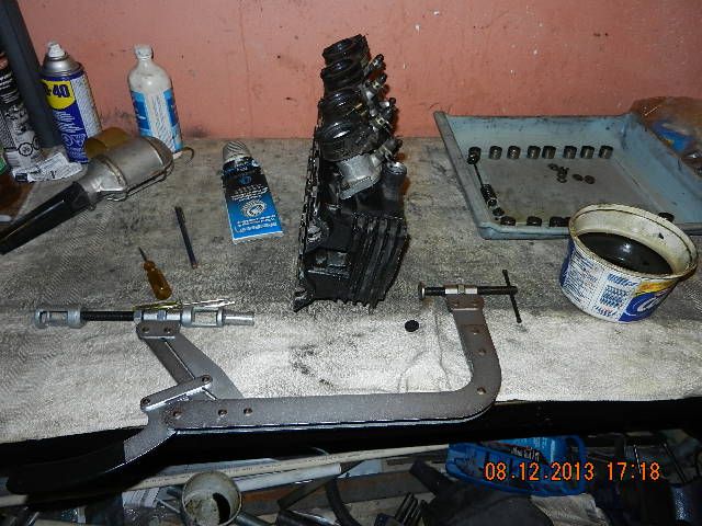
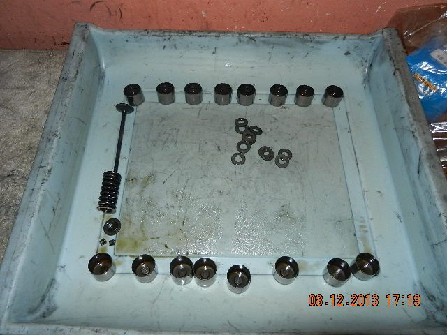
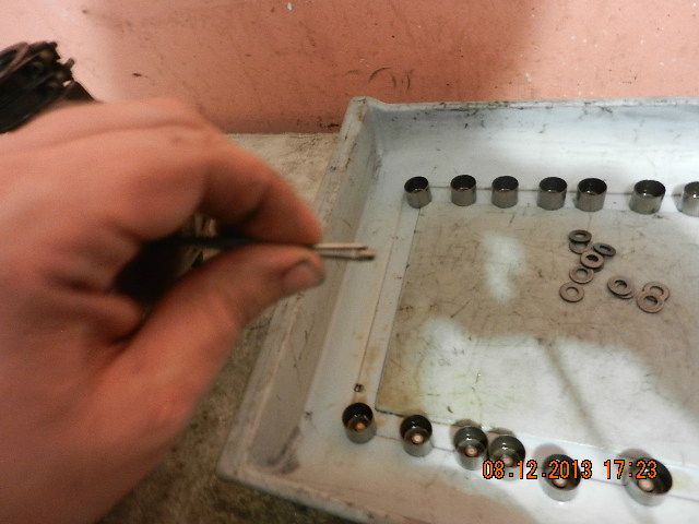
The tricky bit with cylinder head work isn't getting the valves apart ... it's putting them together. It is a finicky job. Here is what's needed: valve spring compressor (customized to suit this cylinder head), a container of oil, some wheel bearing grease, a portable lamp, tweezers, a magnet on a stick (for fishing steel bits out when - not if - you drop them), and various magnetic and nonmagnetic poking and prodding tools. The blue tray at right had all the components laid out in order so that every valve can go back into the same place that it came from. I didn't take pictures until doing the last one.


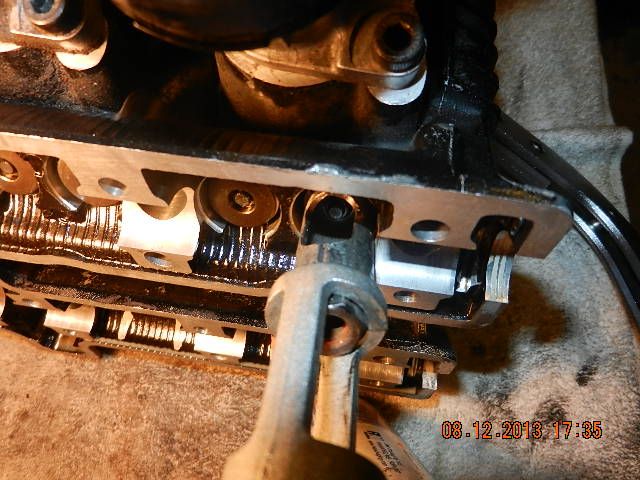
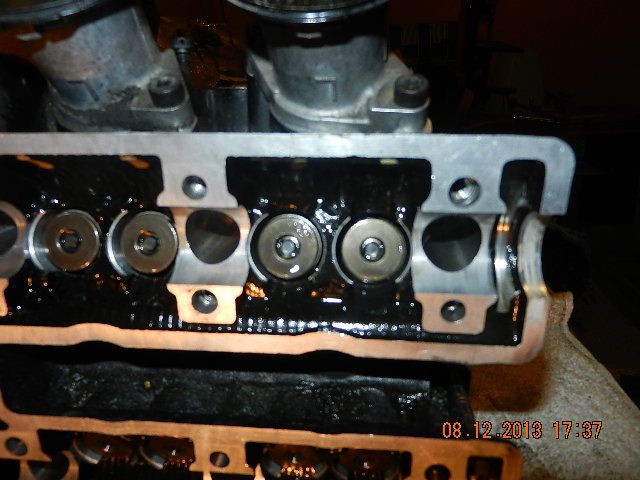
This is the valve mechanism. Not shown (and already in the cylinder head) is a steel spring seat and the valve stem seal. The spring pushes outward on the retainer, and that pulls the valve stem closed through the two little finicky keepers. The camshaft pushes the valve open through the bucket and the clearance-adjusting shim (still inside the bucket in the picture) and that acts on the valve stem directly to open the valve while the spring pushes it shut. The orientation of the spring is important ... it's quite possible to install the spring upside down. In this case, the end with the tight coils goes towards the head and the more open end goes towards the retainer. Ignore the random pile of washers ... those go under the cylinder head nuts later.


After dipping the end of the valve in oil, it gets inserted through the valve guide and stem seal (in the head already) like this ...


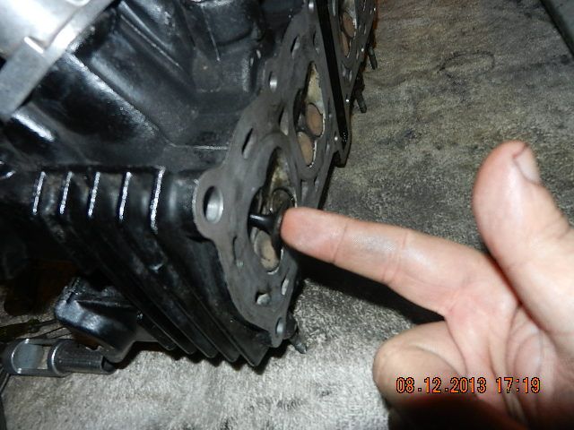
... then a little dab of grease goes on the end of the valve where the groove is, that the keepers will later be locking into.


Then the valve spring goes in as shown - tight end towards the head - with the spring seat already in the head - and the retainer goes in on top of the valve; note the tapered section that will later lock in the keepers. On this engine, the retainers are steel. A lot of newer engines have aluminum or titanium retainers ... that's part of how 600cc bikes nowadays will rev higher than this 400cc bike ... but on the other hand, steel retainers will never break, and that can't be said of a good many newer engines ...


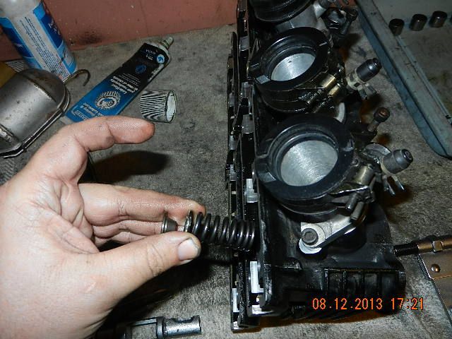
Then the valve spring compressor is used to push the retainer down against the spring, and the other end of it is against the valve with the rubber washer shown before to cushion it.


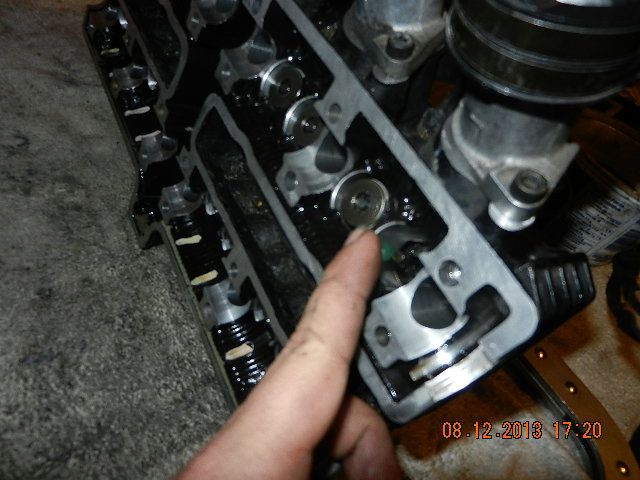
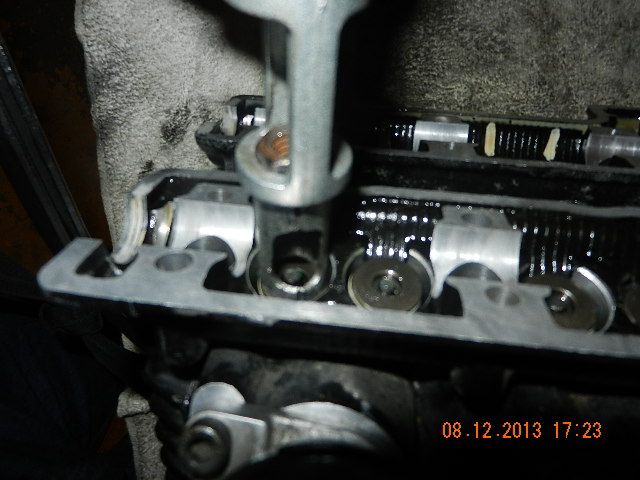
Here you can see the retainer pushed down just far enough to expose the end of the valve stem with the grooves for the keepers, with the window in the tool positioned to allow the keepers to be inserted.


And then comes the son-of-a-gun job. Pick up a keeper with tweezers ...


... and insert it on the end of the valve stem using the dab of grease to hold it in place, then insert the other one, so that it ends up like this.


Or so the theory goes. Do not do this part of the job with small children within earshot. Allow 10 times longer to do it than you think you will need. In reality, there is no room to work, the keepers and your tools have been magnetized (a magnet is the only practical way to pick them up during disassembly - and when you drop them during reassembly), the magnetism is sometimes a blessing and sometimes a curse (which is why one of the non-magnetic poking and prodding tools is a toothpick), and the way the keeper is supposed to be oriented has the heavy end up, which means when you drop it, it always falls the wrong way so that you have to fish it out (magnet) and do it again. After at least 10 tries each, eventually they can be coaxed into sitting in the right spot, and upon removing the valve spring compressor, you have this:


The important thing is that both of the keepers are seated, visibly centered on the valve stem and both the same depth below the surface (which means they are both properly locked into the groove on the top of the valve stem).

At this point, the only thing remaining to go back in the cylinder head are the shims and buckets, which is easy stuff for tomorrow, because with this tough part of the job done, it is Miller time!
 
Last edited:
Cylinder head installed and nuts torqued, oil feed line installed with the bottom banjo bolt and center locating bolt torqued but the upper banjo left loose (reason will become apparent later), camshafts back in place. When re-assembling camshafts, tighten the bolts down evenly to minimize bending loads on the camshafts. When you tighten them down, the forces on the lobes will push the intake cam out of position because the tensioner is not installed yet - it's normal. Note the locating dot on the exhaust camshaft lines up with the mark but the intake camshaft has pushed itself out of position with the slack in the chain.


Installing the tensioner. These have to be reset before installation. On this style of tensioner, remove the bolt on the end and the spring, then push in the one-way pawl (thumb) and push the plunger in (index finger), then it goes on the engine without the spring installed.


Then the spring goes in and the bolt that compresses the spring goes in. For the moment, I am only snugging these because of what I expect to find next ...


And that would be the valve clearance check. This job is a whole lot easier with the engine on the bench than in the bike. On this engine, on the intake side, a 0.10mm feeler should go through the gap as shown and a 0.20mm should not, and on the exhaust side, 0.20mm should go through and 0.30mm should not. In this case, the cam lobe shown allowed the 0.10mm feeler through but with some force behind it ... it's on the tight limit of specs. After rotating the crankshaft one full revolution, the next cylinder over had one valve in the same situation. I would rather have them away from the tight limit.


To avoid having to re-time the camshaft, you can move it away from the lifters as shown and keep the chain engaged in the sprocket. The two offending lifters are out - easiest to do with a magnet on a stick. Both had 1.72mm shims in them - an odd in-between size found only in OEM engines - most likely, this shim has never been changed. Considering age and mileage, can't really complain about that. I had a couple of 1.65mm shims in stock, put those in, re-checked, all good.


Engine is back together with a new valve cover gasket (which is a royal pain to install on this engine and another thing that is far easier with the engine out of the bike). For now, I stuck the old spark plugs in just to avoid accidentally getting anything inside, I'll have to get a new set tomorrow. I also still need to prime the lubrication system and install the clutch ... tomorrow.

 
Here's why I left the upper oil line banjo bolt loose. This is the oil pump drive gear, with everything on the engine assembled except the clutch. It's driven by a gear on the back of the clutch basket. Leaving it off allows the lubrication system to be primed. To do this, simply pour a litre of the oil that will be used for break-in - any cheap non-synthetic 10w30 - into the oil pan and spin this gear in its normal rotation direction with a finger. After a while, after the oil filter housing fills up, the sound of air bubbling through somewhere from the depths inside, reveals that the oil is working its way through the engine. When a little bit comes out of the end of that oil line, the oil is up to the top end. Torque the upper oil line fitting then spin the oil pump manually a few times more to fill the cylinder head and camshafts. Later on, the moment the engine cranks, it will have oil pressure


These are the parts of the clutch basket. Look at the diagrams in the book carefully - it's quite possible to put these parts together the wrong way. In this case, the thrust washer with the grooves in it goes inside the clutch, to fling oil at the clutch plates.


With the clutch basket and clutch hub installed and the nut in place, the release mechanism goes together. The little steel ball was stored in a great big ziploc bag together with all the other clutch parts so that it wouldn't wander off and disappear when I needed it!


Air tools are the only practical way to tighten the clutch hub nut, then there is a tab on a wavy washer that is bent over the nut to stop it from going anywhere.


Clutch plates installed, ready for the pressure plate. Note the alignment mark - the dot on the pressure plate has to line up with the arrow on the hub. You can put the pressure plate on 5 different ways, but only one of them will work!


Springs go in, bolts get torqued to a very low setting (7 N.m). I re-used the clutch that was in the bike, because it was only recently replaced (last year).


One other thing to make sure of at this point is that the shift shaft mechanism (lower left in photo) is properly aligned on the shift drum with its spring fingers centered on a locating pin. A projection on the clutch cover stops the shaft from pushing out once the cover is in place.


And with that, and a new set of spark plugs installed, and the correct amount of break-in oil already in the engine (you can see the window), the engine is done and ready to go into the frame. Major milestone!
 
Last edited:
What's the benefit of priming it by hand, rather than just turning it over with no fuel?
Any particular reason for 10w30 over 10w40 for break-in?
 
Last edited:
If there is a choice in the matter, I'd rather not have moving parts moving at all without oil being fed to them. Even with no fuel, there is still load from compression. Not all engines allow the oil pump to be operated independently of the engine. On a traditional small block Chevrolet, you always spun the oil pump with a drill motor before installing the distributor to prime the engine. Can't do that on an LS where the pump is together with the timing housing on the front of the crankshaft.

For 10w30 vs 10w40, there's no significant difference, they'll both have (roughly) the same viscosity during cold starting ... but 10w30 is cheaper! This oil is only going to be in the engine for the first few minutes of running. You intentionally don't want the break-in oil to be "too good" or "too slippery" ... it needs to let the piston rings seat.
 
Man you've put some work into this! Should be well worth it in the end!
 
Engine in, front brakes on. Front brakes are being left stock, right down to the brake lines. They are actually FZR600 brakes and are plenty good enough. Not broke ... don't fix.


Next chore ... the wiring harness.


This looks scary ... but then I realized that the best thing was to think about how they would do this on the assembly line, and do it the same way. On the line, all the brackets and gadgets that the harness has to run through or plug into or attach to would be in place, then just lay the harness in and hook everything up. So, I took the ignition coil bracket and rear fender parts off the harness (good excuse to clean some areas that normally there is no access to) and attached them to the bike.

And, there is a minor change in plans with regards to the ignition wires. I got new plug caps (which I will use) but I've had 7mm ignition wires on order forever, and they have not shown up. Plan B, go to an auto parts store in the hope of adapting a set of car ignition wires. Found some that were long enough and looked about the right diameter ... but, no such luck. They are 7.5mm diameter and won't fit the ignition coil.

So, unless I find some 7mm wires in the next day or so, I'm going to keep the stock ignition wires and use the new plug caps. The plug caps seem to be the weak point, anyhow.
 
Sweet...now I know a guy who can guide me in the burnt up wiring replacement for the YZF! I am pretty sure electrically, they are basically the same as an FZR- most of the rest of the bike is already anyways.
Someday I am gonna pull that motor out and truly replace 2nd gear...then maybe transplant it back into Josh's streetbike and ride it.
 
Brian, was just reading thru your thread. Great write up and very informative.

Keep posting.


Jeff
'87 RZ 350
 
Yesterday's snow day (plus GTAM being out of commission) meant I had no excuse not to work on the bike.

First step - ignition coils. It was mentioned earlier that 7mm ignition wire has been on order for quite a while but has not shown up. Plan B was to use the stock wires with the new plug caps. No dice. The new plug caps are slightly shorter and have to be installed in an orientation that requires the wires to be a bit longer. Oh well, since there wasn't a problem YET with the stock ignition, I'm leaving it alone, leaving the plug wires on order, and if/when they show up, they'll go in the spares shelf so that I'll have them when I really need them.

Next - Re-installed the wiring harness. I found that the best way was to start at the back and work forward. I bolted the ignition ECU down, reconnected the taillights and rear turn signals, installed the main ground strap (it connects to one of the crankcase bolts at the back of the engine, which had been left loose earlier for this reason), positioned and re-installed the voltage regulator, fuse box, starting motor relay, side stand switch, connected the rear brake switch, plugged in the stator and crank position sensor. The connectors that lead to the engine fit into a pocket on the frame which is shared with the clutch cable, so it made sense to re-thread the clutch cable through at this point, even though there's nothing to connect it to yet, more on this below. Plugged in the ignition coils, routed the wire for the radiator fan, installed the fan relay. Then the part of the harness that leads to the front of the bike can be fed through the hole in the frame. At that point, I installed the front fairing bracket with instrument cluster, plugged in the instruments and the left and right switchgear, then installed the headlights and plugged them in.

I installed the 8-cell lithium battery that came out of one of my other bikes (it proved to have not enough guts to start that one, but this one has a smaller engine so it ought to work) but have left the ground cable disconnected at the battery end, just to be safe.

The voltage regulator is slated for replacement with an upgraded unit (necessary for properly charging the lithium battery), but for initial startup, the stock one will do. I need to grab some solder and wire for extending the harness.

Then ... Cooling system. All of the coolant pipes have been put in with new O-rings - the stock ones are probably metric, but given their nature, standard ones are close enough and are available cheaply from Able Gasket and Seal.

Next, carburetors. To address a minor cold-engine drivability issue from last year, I took the opportunity to raise the needles by one groove.

Airbox ... and not unexpectedly, ran into a traditional FZR400 bugaboo ... hardened-up airbox-to-carb boots. The old ones could not be coaxed in place. Earlier, when I took the airbox off, I had found that one of them had distorted out of place and was leaking slightly ... explains the messy residue in the area. This is such a common headache with these bikes that I keep a fresh set in stock, so this was easily fixed (and now I'll order a new set to replace stock - internet says they're still available, we'll see).

Fuel tank ... The fuel lines and fuel filter needed replacement. I grabbed some 1/4" fuel line from Canadian Tire. Unfortunately, the total length needed from petcock to fuel filter to fuel pump to carbs ended up just a smidge too short with what came in the package, and I'm not happy with where the fuel filter ends up in the bike with the tank installed (it's pressed up against the crankcase vent hose with the fuel hose squashed between the crankcase vent hose and the bottom of the fuel tank), so I'm going to have to re-do this a bit.

It is really close to first start-up. Still need to re-work the fuel lines and install the exhaust, and connect the clutch. I found out why the countershaft sprocket was stripped. I am using a 520 chain in this bike - stock was 428. The stock countershaft sprocket has a projection on each side. To align the chain, I have to use a 520 sprocket from a GSXR600 which is a thicker sprocket but only has a projection on one side. It appears that the total thickness of that sprocket is thinner, resulted in the countershaft nut bottoming out before it fully clamped the sprocket in place. I'm going to fix this by doubling-up the washer that you bend over the nut to stop it from backing off. Already have the washer on order, but until it comes in, I can't hook up the clutch, because the release mechanism is built into the sprocket cover.

It has been said that the last 20% of any given job ends up taking 80% of the time ...
 

Back
Top Bottom