Bike stalled in traffic, wouldn’t start | Page 2 | GTAMotorcycle.com

Bike stalled in traffic, wouldn’t start

"Alternators are used in modern automobiles to charge the battery and to power the electrical system when its engine is running. Until the 1960s, automobiles used DC dynamo generators with commutators. With the availability of affordable silicon diode rectifiers, alternators were used instead."
Alternators are far more efficient at producing power at lower engine speeds and they don't over-power at high speeds, they output alternating current that needs to be altered to produce the direct current required by your battery and devices. A DC dynamo generator like you would find on a vintage BSA outputs DC. Dynamo's look like a little electric motor except you spin it and it outputs power instead of using power to turn it.

Your bike might be running on 2 coils right now and there will be no way to know that until you test the output and or impedance of your 3 coils independently.
 
You know it's an alternator IF it has a rectifier. Having a rectifier infers it outputs AC, ALTERNATING CURRENT, ergo ALTERNATOR.
Alternators are easier to regulate than generators. The problem with a generator is that you are either not charging at idle/low speed or you're over charging at high speed. Pick one.
Alternators don't need to be three phase, some are one or two phase, I've seen 6 phase. You could wire as many phases as you want/need.
Alternators are much more efficient than generators, meaning they will make the same electrical power as a generator using less engine power. A LOT LESS, like a third.

As an aside: A generator is an electric motor. Spin it and you take power out. Put power IN and it will spin. (You may have to spin it to start it. Building a electric motor with a commutator is easy, getting it to start spinning is not) Some motors use the generator as a starter. Neat huh?

A Shindengen SH775 is a shunt regulator, that uses Mosfet diodes. Mosfets switch faster and produce less heat than regular diodes.
Most motorcycles have a permanent magnet alternator, that work as hard as they can 100% of the time, which produces EXCESS power. The regulator "SHUNTS" that excess power to ground.
Most cars have an alternator with a wound electro magnet rotor, with the regulator in SERIES with that winding in the rotor. Increase the power in that winding which increases the magnetism in the rotor and the alternator output go up, decrease the power in that winding, the output goes down.
SOooooooo you can't swap a shunt regulator for a series regulator.

... and then there are "A" or "B" types of series regulators. One regulates the positive side, one regulates the negative side (I can never remember which is which). Dodge and Bosch regulate the negative side of the circuit, Ford regulates the positive.
I hate to disagree, but to my understanding an SH775 is a series RR as is a compufire. They can be found used on EBay for approx $40. I have one on my GS1100 that replaced the stock shunt RR. So you can swap a shunt for a series RR.
 
terminology

alternators have a stator
the part of the mechanism that does not rotate
hence the name

it's the part of a motorcycle alternator that fails
as it has the windings on it

not much to go wrong with permanent magnets
on bikes we generally just refer to a stator failure
but we are talking about part on an alternator
 
MOSFET is not a diode it's a transistor.
10213-01.jpg

3 connectors plus the ground tab, in the most simple terms it's a fancy electronic switch.

Electronic symbol as it would appear on a diagram:

Symbols-of-enhancement-mode-MOSFET.jpg
 
Last edited:
not much to go wrong with permanent magnets
on bikes we generally just refer to a stator failure
but we are talking about part on an alternator
I've seen rotors suffer physical damage or demagnetize over time and fail. Definitely its the least likely scenario.
 
If you think you have a charging/battery problem:

FIRST, before you do ANYTHING else; CHARGE THE BATTERY, at no more than 10% of it's rated capacity. Then let the battery sit for a couple of hours.
After it rests, the battery should put out at LEAST 12.7 volts. If your battery won't hold 12.7V, you have a battery problem.
Now put the battery in the bike and connect it.
Read the battery voltage, a drop of 0.1V is OK, but not much more.
Turn on the bike, don't start it, and it shouldn't drop more than 0.5V (Some bikes the headlight will come on, some not. Half a volt is OK if the headlight comes on. This where experience kicks in....)
If you get a big drop when you turn the bike on, start pulling fuses, one at a time, to figure out where the big draw is.
Try to start the bike WHILE monitoring the battery voltage. If your battery is up to snuff the voltage shouldn't drop below about 10V, and should hold that 10V for 10 seconds of cranking.
If you've got this far, your battery seems to be OK.

Now check voltage at idle. As long as it's higher than the battery at rest, you're OK. Newer bikes will put out more at idle than most older bikes, so let's generalize.
Check voltage at 2000 RPM Should increase some
Check voltage at 4000RPM Should be above 13.7V for lead/acid battery, about 14.5 for anything else.
Set your multi-meter to AC voltage and check across your battery terminals. You'll see some AC voltage but not much (again this where that experience kicks in) UHmmmm less than 6V AC, IDK, but if you see like 12V AC you know/assume you have rectifier problems.
Most bikes have the rectifier and regulator built into one box so you can't test, directly, either component, so you have to make assumptions.
If you've made it this far, you seem to have a functioning regulator and rectifier.

To test the rotor and stator you should remove them and examine and clean them. Your manual will have a test procedure....
I have a couple of problems with their test procedures.

1) You're testing with a multi meter, that is powered by a 9V battery at best.
Ideally you want to put an EXCESS of voltage into it to test the insulation (You want a power line insulation tester, called a "MEGGER" that puts thousands of volts into the stator. I don't have a "MEGGER" anymore, so I test stators with 110V 15A AC. Where the fire starts is where the problem was....)(I put a light bulb in the circuit to limit current. I'm not crazy).

B) I'm lazy.

Being pragmatic, the first test I'll do on the stator is to check AC output across the three legs. You want to see about 70V AC on three legs, all the same.
A to B B to C A to C
If all three are not the same, you have a stator problem. Quick and dirty.

You have to do this final stator test because it is possible to have one of three phases dead/wounded and the alternator will output adequate voltage but not enough amperage to charge the battery.

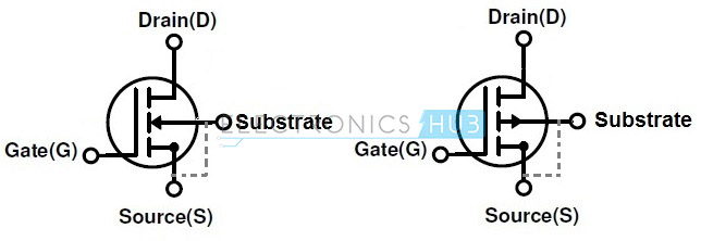
This is all a generic, quick and dirty diagnostic, that the average user, that can figure out a multi meter, can follow and use. Yes, Trials, I know that a mosfet is a transister, that in the circuit we were talking about is used to replace the diodes, because they're faster switching and they run cooler, BUT the average user here has at best a basic grasp of what a diode is and what it does, so I generalized. SORRY. You'll notice the guy that brought up mosfets is still insisting the Shindengen SH775 isn't a shunt regulator.

Calling a stator a stator is basic nomenclature. In a mechanism that has a rotating part and a stationary part, the stationary part is called the stator. IE: hydraulic motors have stators.

Rotors come apart all the time. CBs and EXs are famous for rotors grenading. When the EX rotor grenades, it has those "composite" magnets, the magnets disintegrate and circulate magnetic mush throughout the motor. YUMMY. It packs the oil galleries in the crankshaft and that's that.
 
The MOSFET is being used to regulate it can't rectify to save its life.
Diodes allow power to flow in only one direction; that is why they can be use to rectify

"You have to do this final stator test"
Why is it the final test and not the first test :unsure: you guys never had to have a coil rewound or replaced before?
Copper windings coated in varnish are not exactly foolproof.
I charged by the hour, when I wanted to find an electric problem, I always started with the source and worked down stream. It keeps the billing hours low and the customers happy.

The battery is your power reservoir, a disposable item at best, if in doubt, ... not worth your time to mess with an 100 dollar battery when it is 4 or more years old in my motorcycle experience. Replace it with a brand new cheapest one you can buy that meets or exceeds specs, charge it up nice and now you can forget about that as being a problem for 3 more years :geek:

I use a little tiny dual trace oscilloscope to test my alternators, a oscilloscope trace blows away multi-meter testing.
 
Last edited:
Why is it the final test and not the first test :unsure: you guys never had to have a coil rewound or replaced before?
Copper windings coated in varnish are not exactly foolproof.
I charged by the hour, when I wanted to find an electric problem, I always started with the source and worked down stream. It keeps the billing hours low and the customers happy.
The battery is your power reservoir, a disposable item at best, if in doubt, ... not worth your time to mess with an 100 dollar battery when it is 4 or more years old in my motorcycle experience. Replace it with a brand new cheapest one you can buy that meets or exceeds specs, charge it up nice and now you can forget about that as being a problem for 3 more years :geek:
You can start at either end, the result is going to be the same.
Batteries are most likely to fail, easiest to check - load test, if no good replace.
On most modern motorcycles the reg/rect is next easiest - no or low output you've got a problem.
Rotors/Stators are next - no output to the reg/rect then by process of elimination you know where your problem lies.
Usually, in my experience, more time is spent pulling off plastic and finding the appropriate connections than actually doing the tests, that's where a shop's labour time comes in. Bring it in as stripped as you can and a good mechanic with the right diagnostic tools can usually find the source of the problem in less than half an hour.
 
...
To test the rotor and stator you should remove them and examine and clean them. Your manual will have a test procedure....
...
What!
:unsure: why would you not just poke a test probe into the a** end of the plug with the 3 yellow wires that is hanging outside your engine?
and why are you guys bent on make in it so complicated for the poor OP.
 
The thing on the electric schematic labeled "generator" is a 3 phase alternator. you can tell because it has been drawn as 3 separate coils with 3 identical colour wires, all of which go directly to the rectifier and regulator. A rectifier changes AC alternating current into DC direct current using diodes. The 3 coils are arranged around the armature in 3 different positions so the electric output from each coil is out of phase to one another.
The regulator/rectifier combines the 3 phase AC output into a relatively smooth DC output.
... Now lets say One of those coils is putting out too much or too little power because it has an internal short :| You need to know that and you can't test it at the battery.

MOSFET is not a diode it's a transistor.
10213-01.jpg

3 connectors plus the ground tab, in the most simple terms it's a fancy electronic switch.

Electronic symbol as it would appear on a diagram:

Symbols-of-enhancement-mode-MOSFET.jpg

What!
:unsure: why would you not just poke a test probe into the a** end of the plug with the 3 yellow wires that is hanging outside your engine?
and why are you guys bent on make in it so complicated for the poor OP.

you are a site treasure trials
don't ever change brother
 

Back
Top Bottom